How to procedurally generate DMF file for inflatable structures?
June 2023 - August 2023 at Pneuhaus under guidance of August Lekrecke.
Over the 8 weeks, I developed C# scripts in Grasshopper for generating production files for inflatable structures. This workflow accelerates entire design process, from form-finding, patterning, labeling, unrolling, and simulation, adaptable to various input topologies and pattern types. It uses the half-edge data structure to enhance performance and robustness.
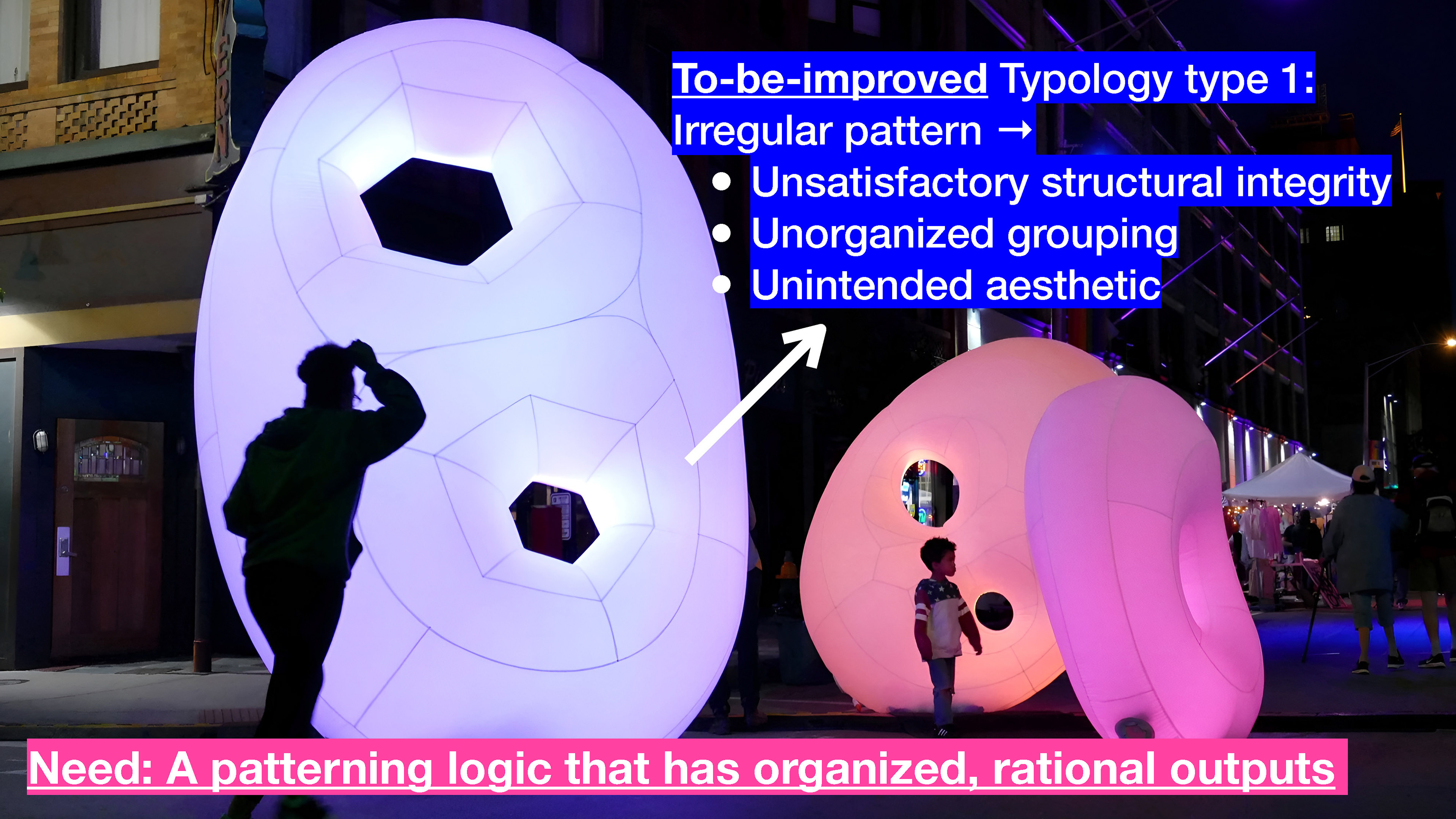
Inflatable Structure example 1: Cloud Lights by Pneuhaus
Solution 1: Closed Boundaries (2D Input)
Turn almost any flat doodle drawing into manufacturable inflatable.
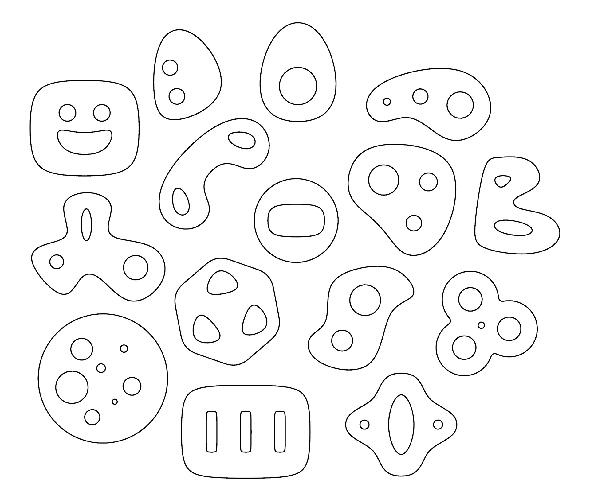
Some input tests
Developable Panels
The grasshopper definition enables users to freely modify the patterning design for aesthetic, structural, and manufacturing purposes. The segmentation count, length, width, seam alignment, and other parameters can all be easily adjusted based on the needs.
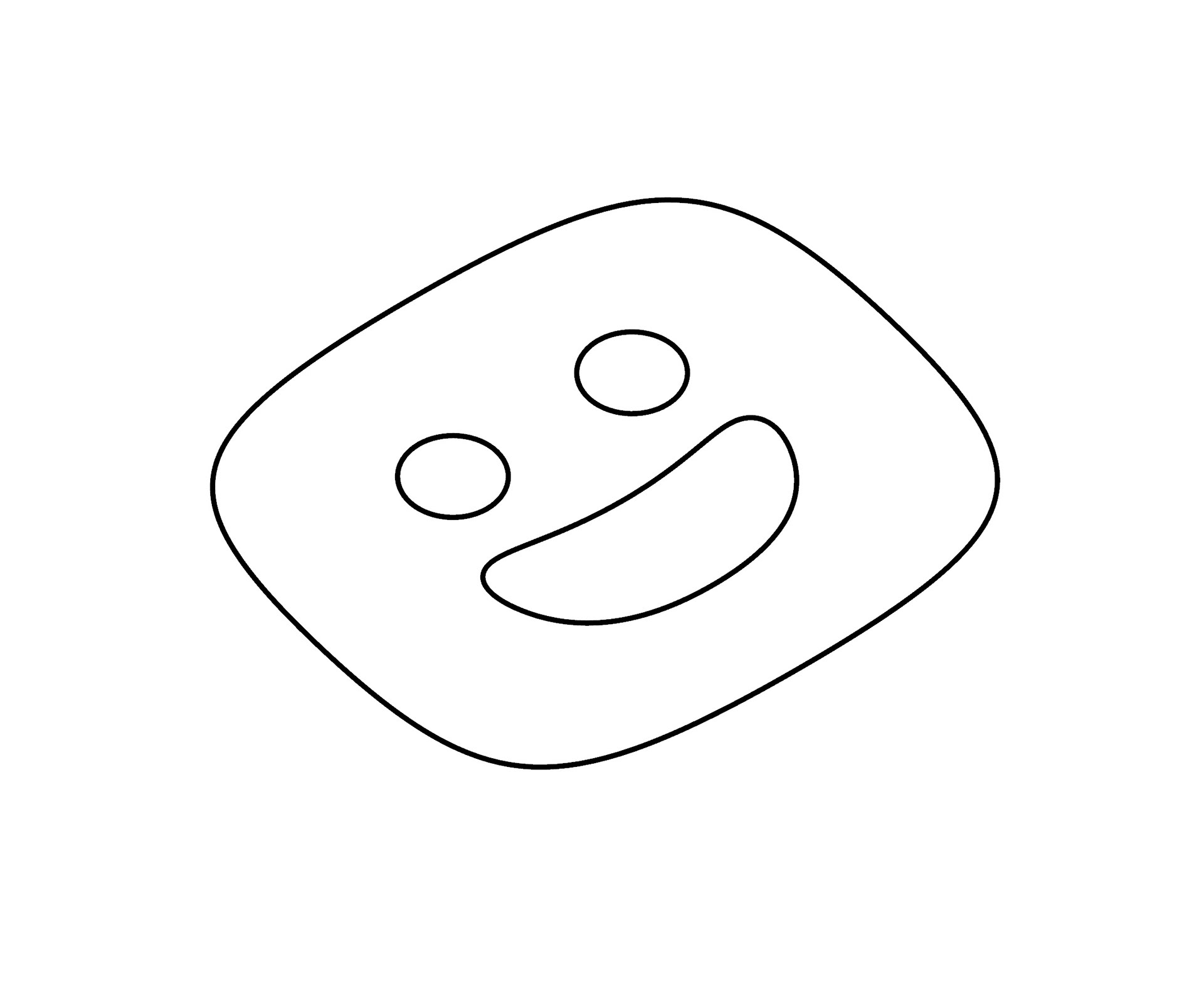
1. Draw input boundaries
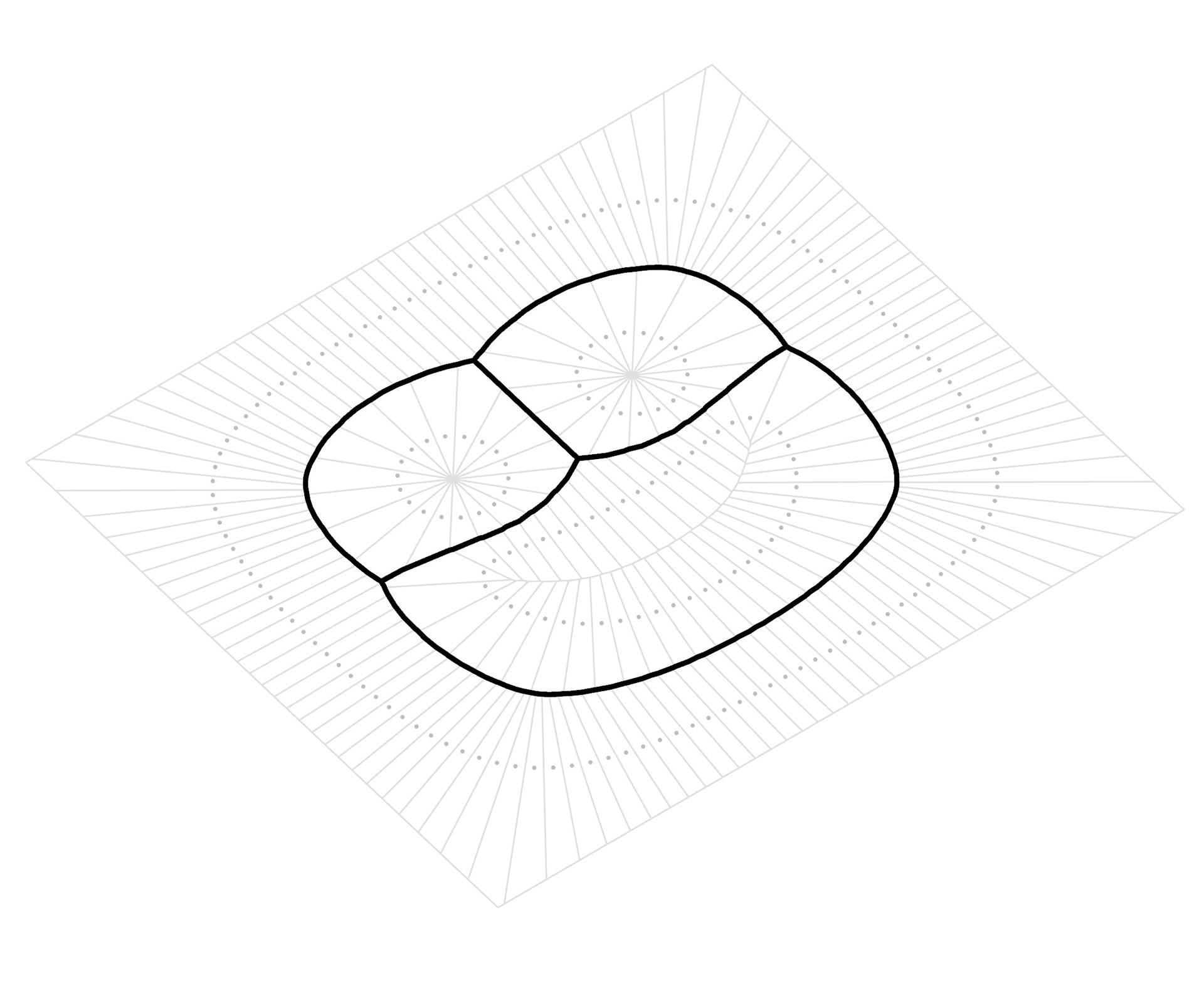
2. Extract skeleton
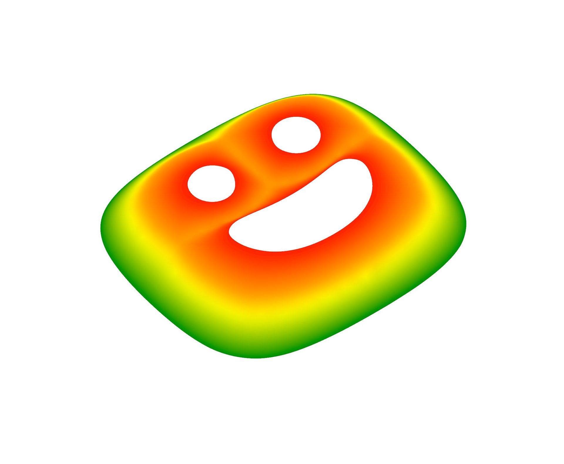
3. Construct mountain
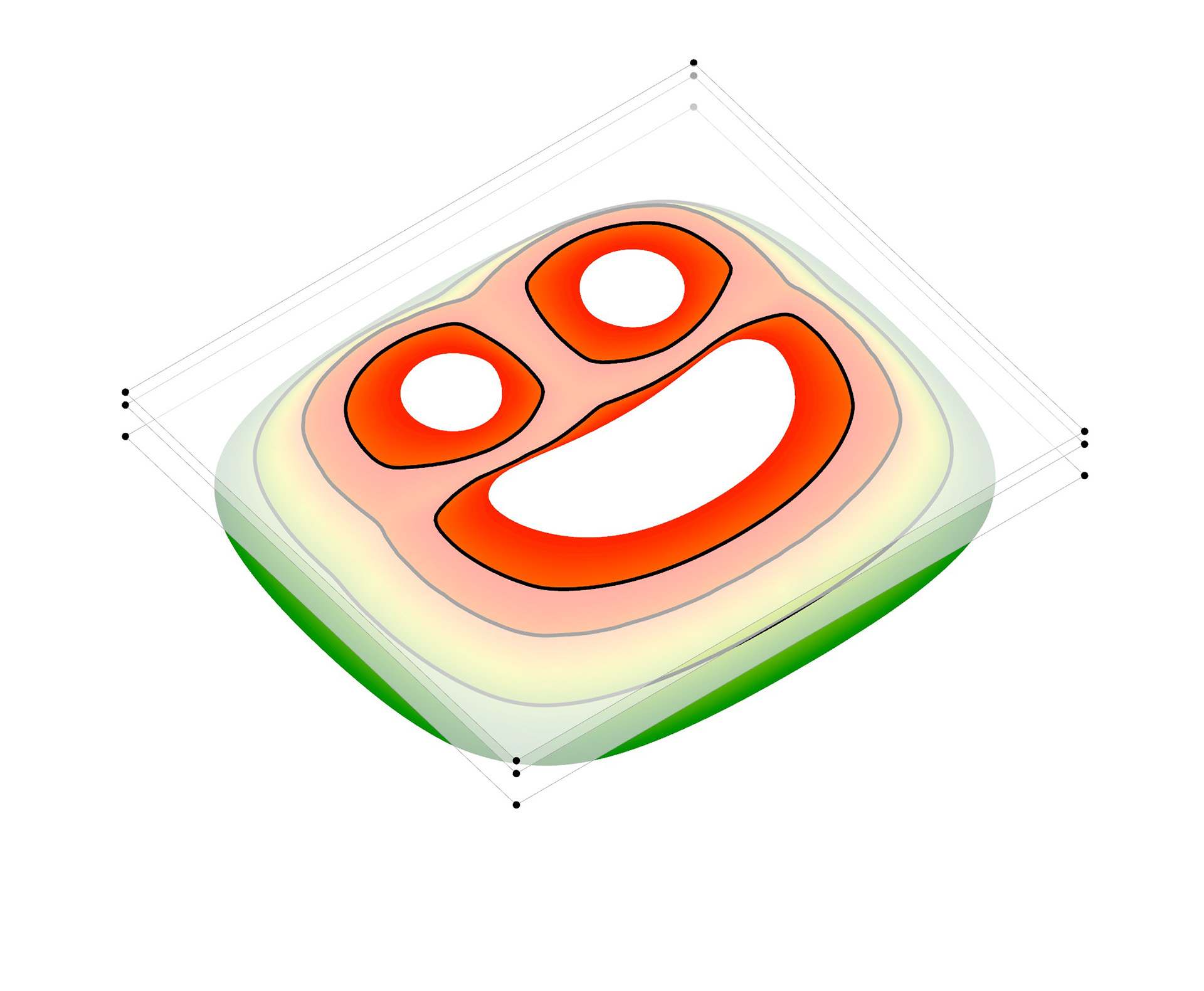
4. Get contours
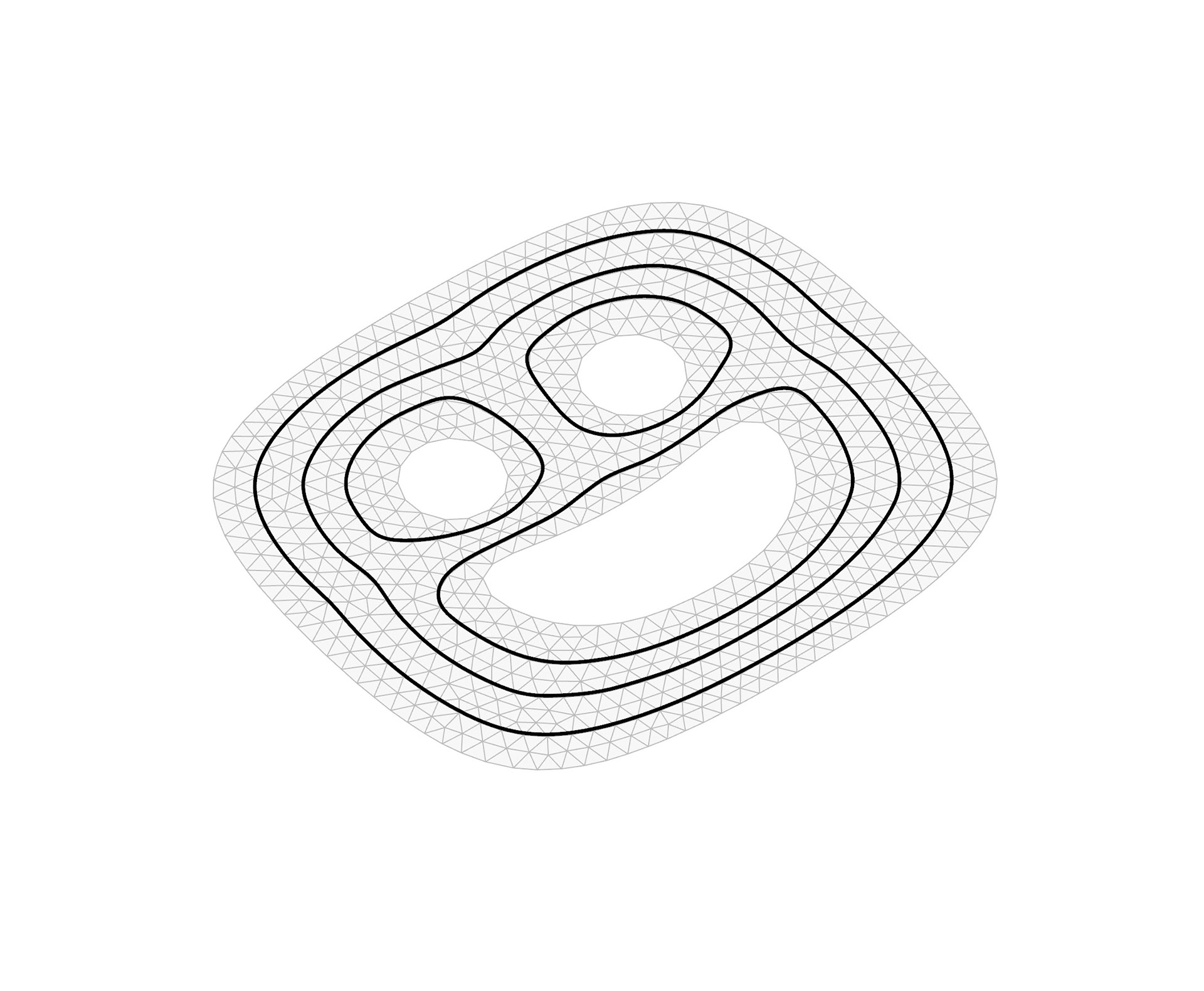
5. Triangular remesh
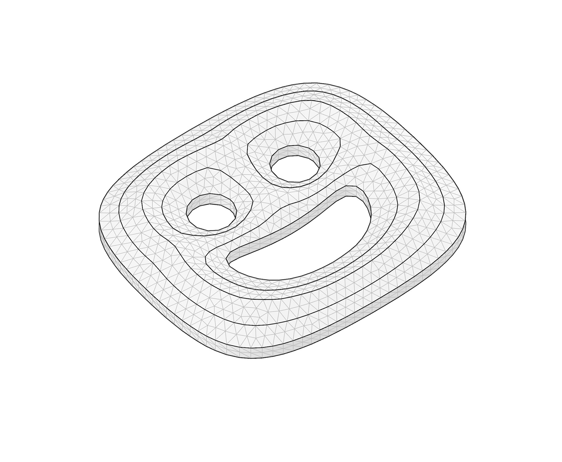
6. Add volumne
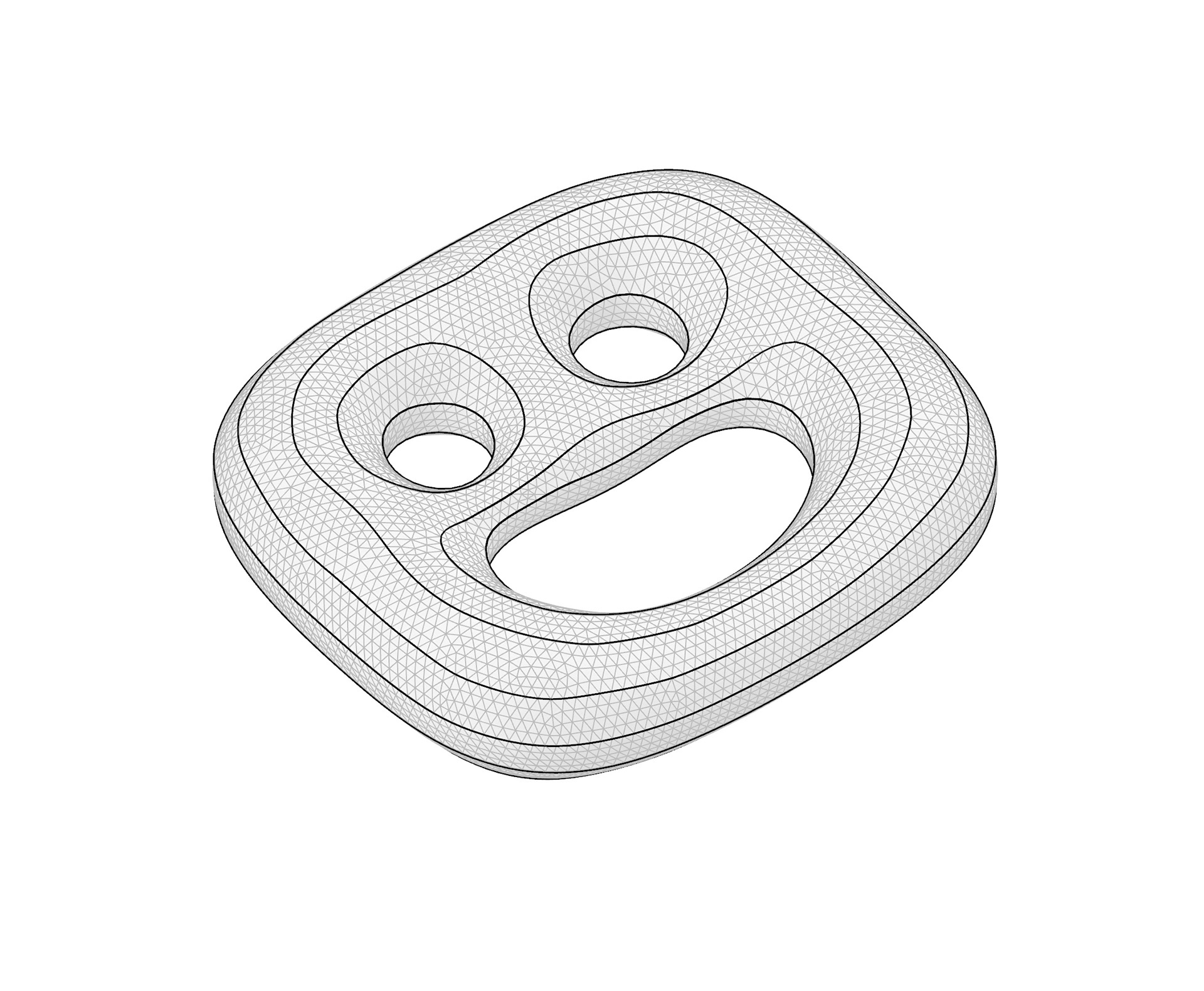
7. Subdivide and simulate inflation
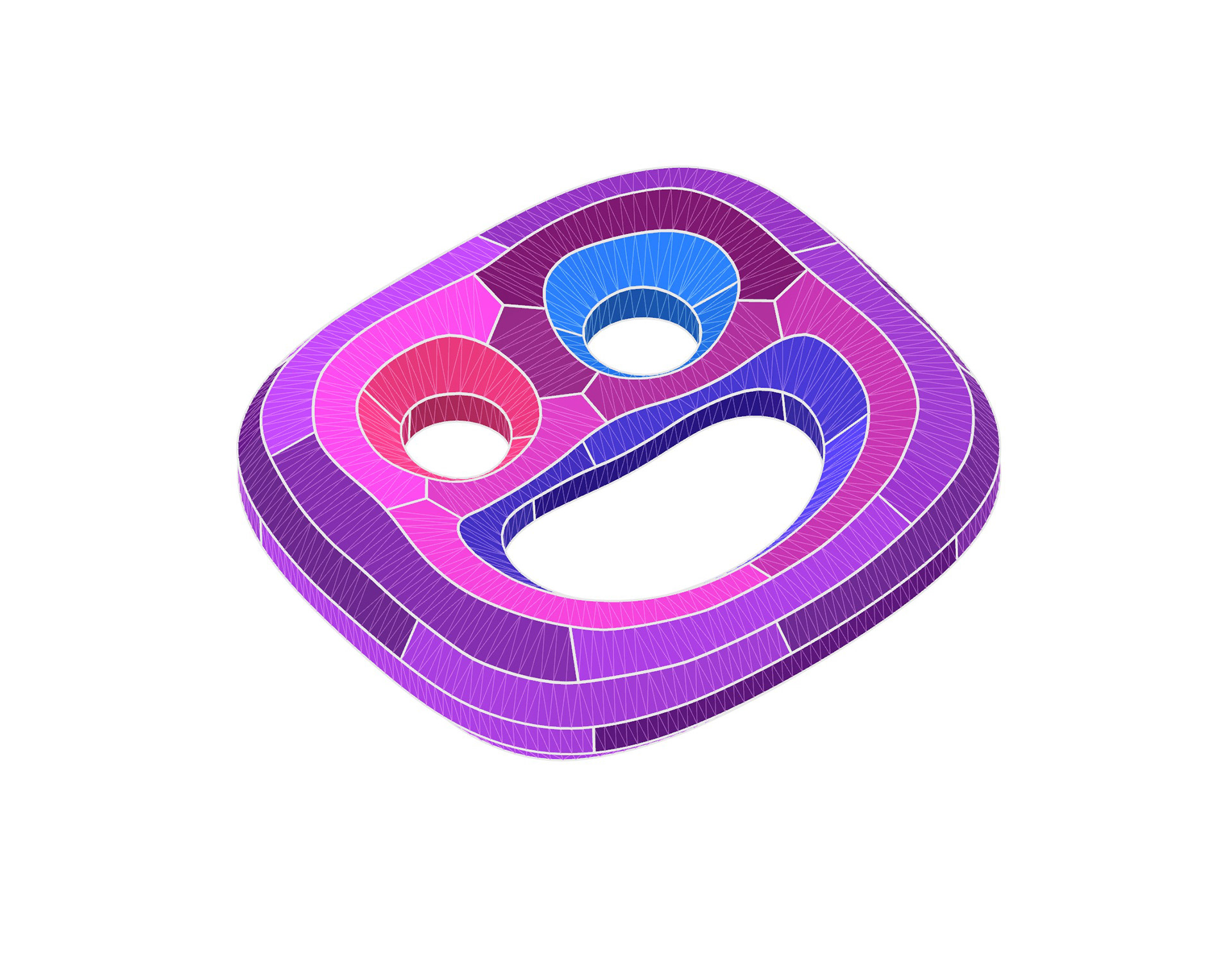
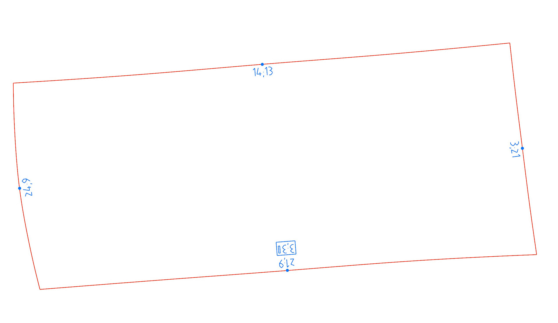
8. Finalize pattern
360 View of the final panels
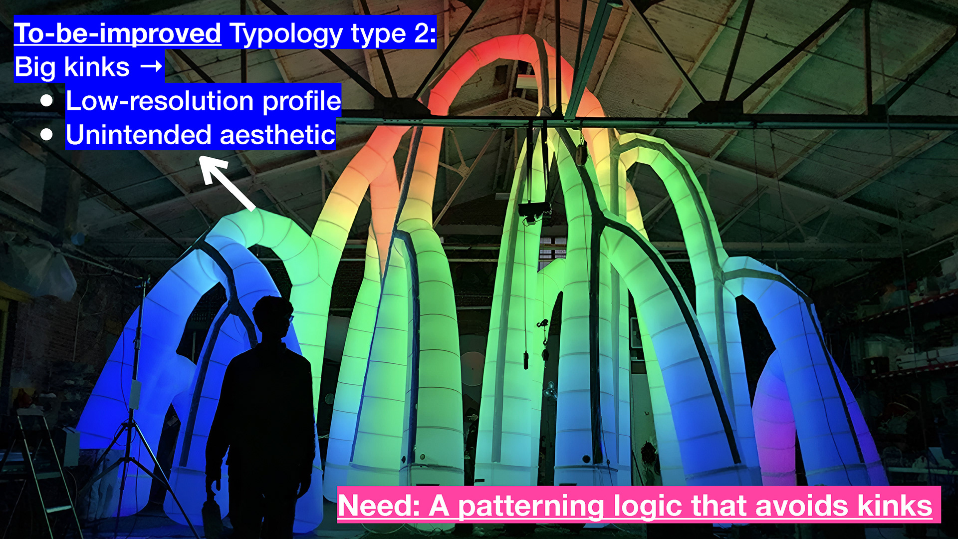
Inflatable Structure example 2: Grove by Pneuhaus
Solution 2: Line Networks (3D Input)
Turn almost any 3D line networks into manufacturable inflatables with a smoother output profile.


Adaptive to Design / Manufacturing needs:
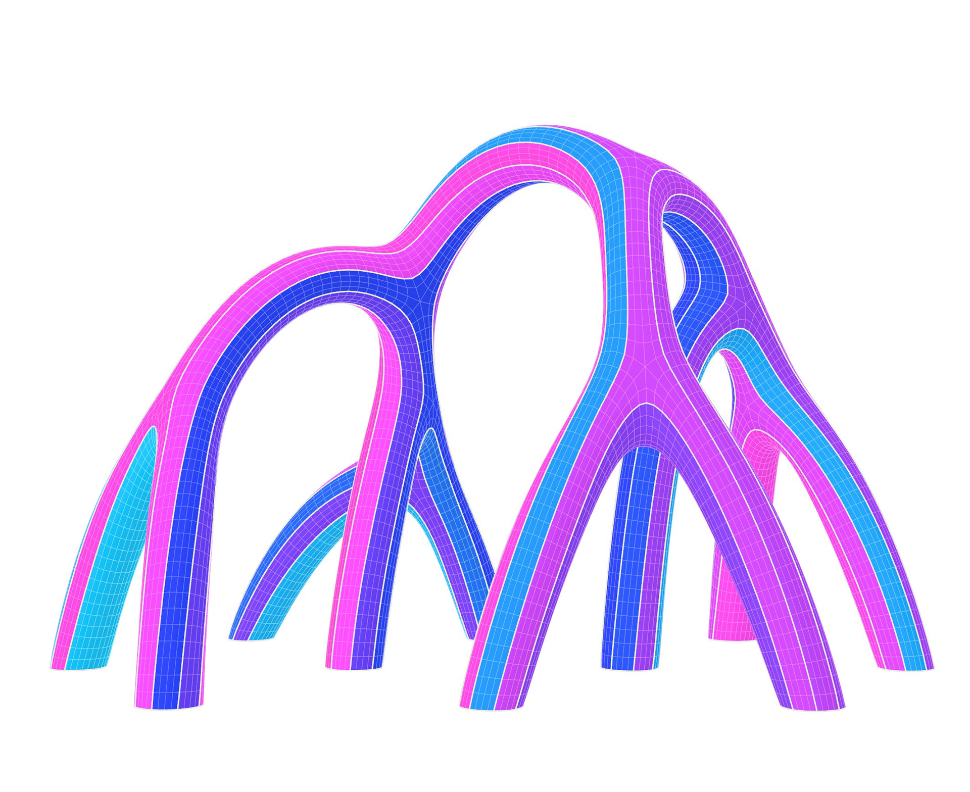
The below animation demonstrates the adjustable nature of the complex strip's width (highlighted in blue), while the simple strip's patterning (shown in grey) also automatically adapts to the width change. This feature, specifically requested by my advisor, introduces greater flexibility in fine-tuning design and fabrication processes.
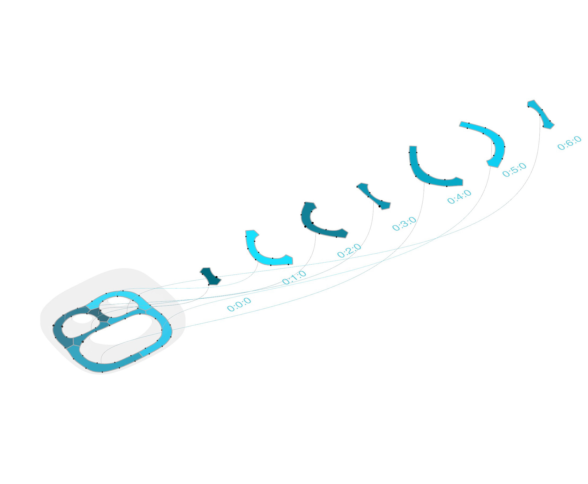
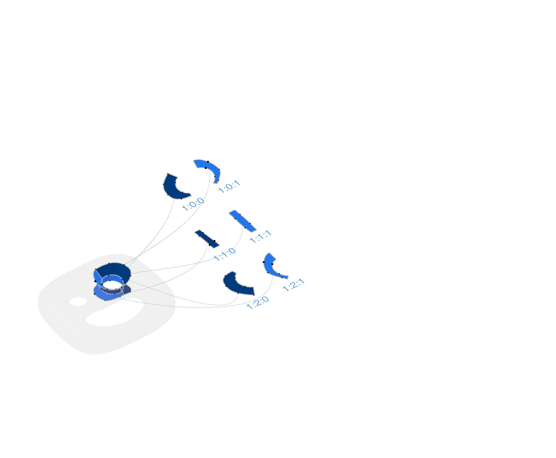
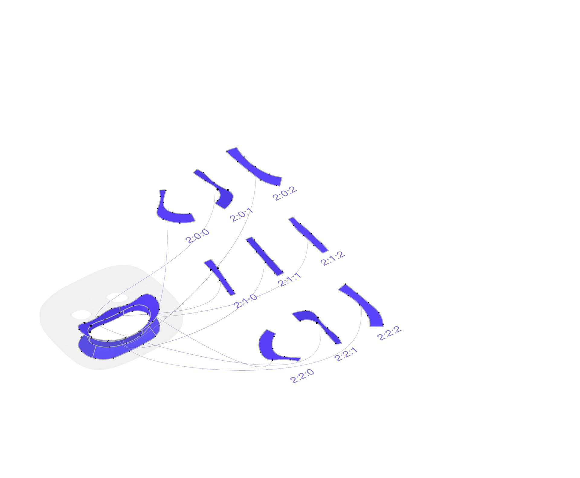
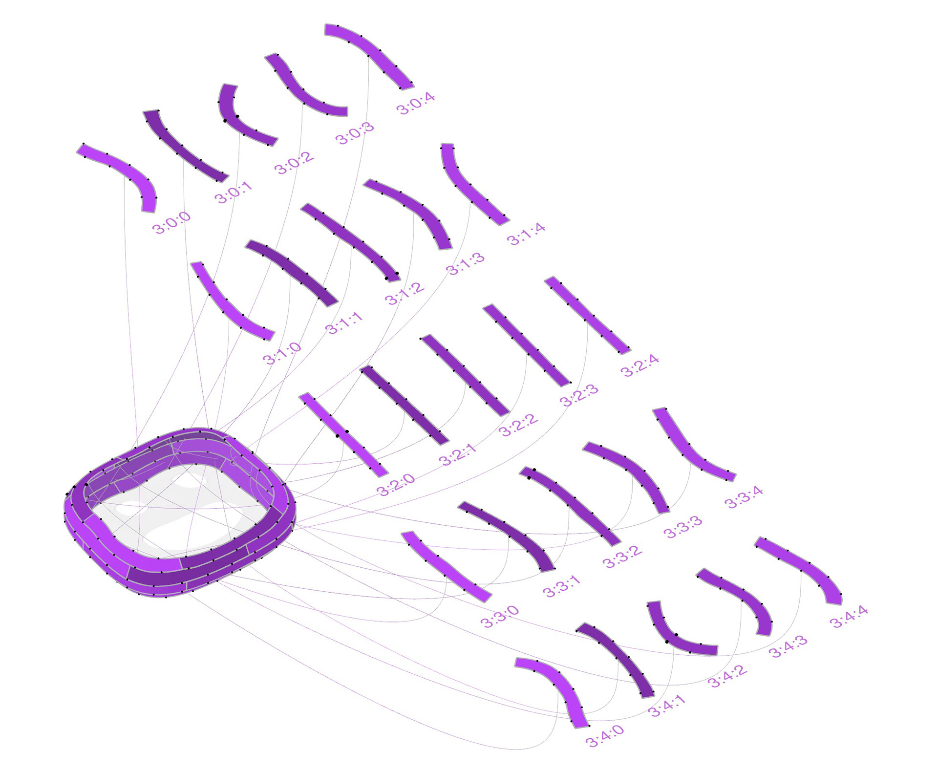
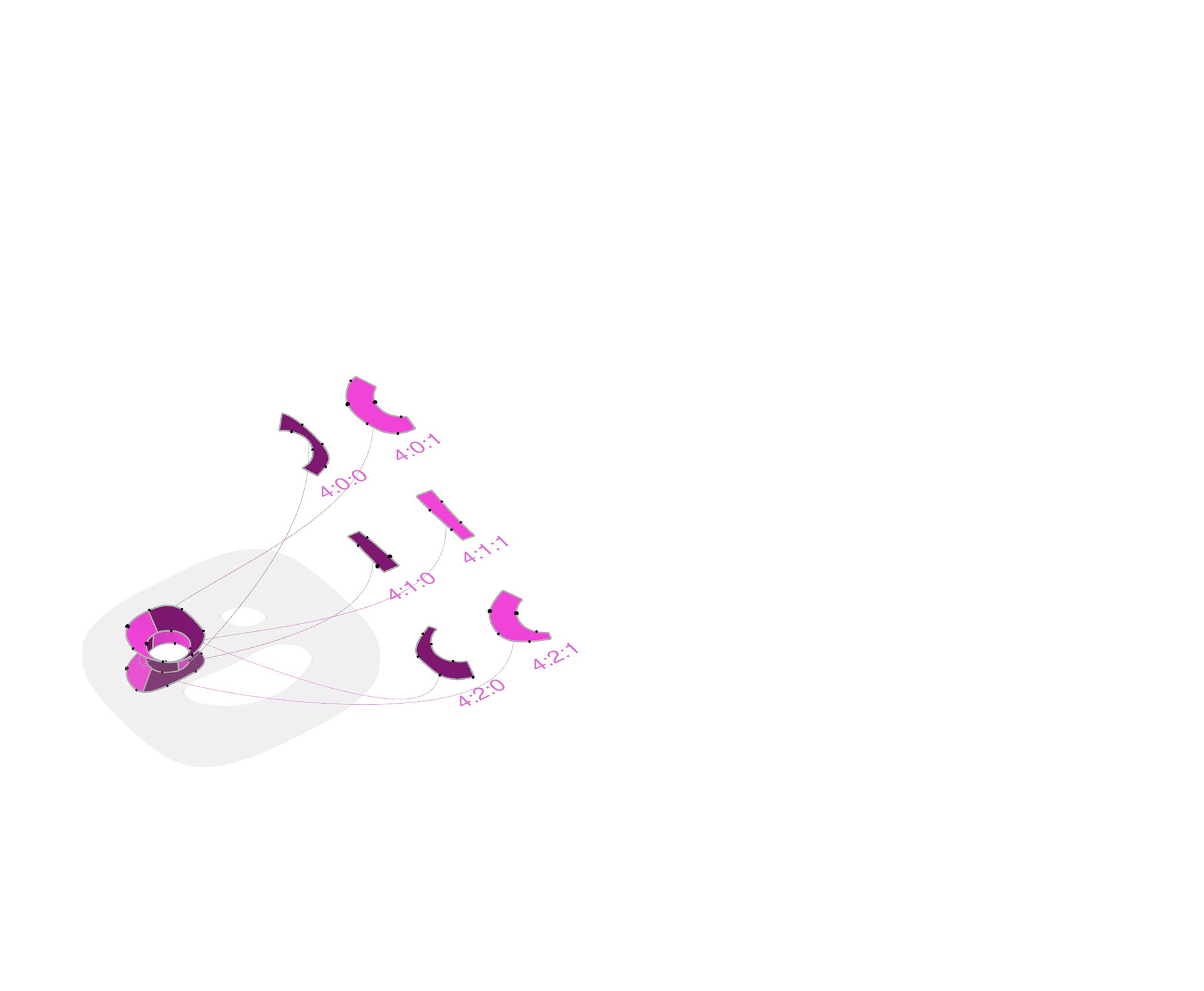
Assembly Guide I: Group Search
The diagram and animation above show the general steps and the mapping between 3D geometry and 2D flattened pieces. The GIF on the right serves as a group dictionary that shows the overall assembly sequence.
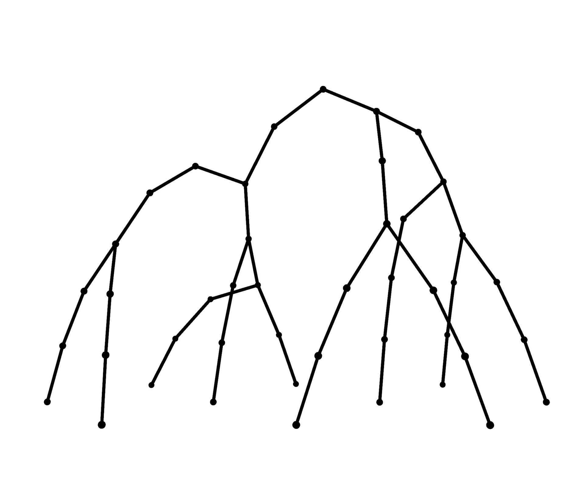
1. Draw connect lines
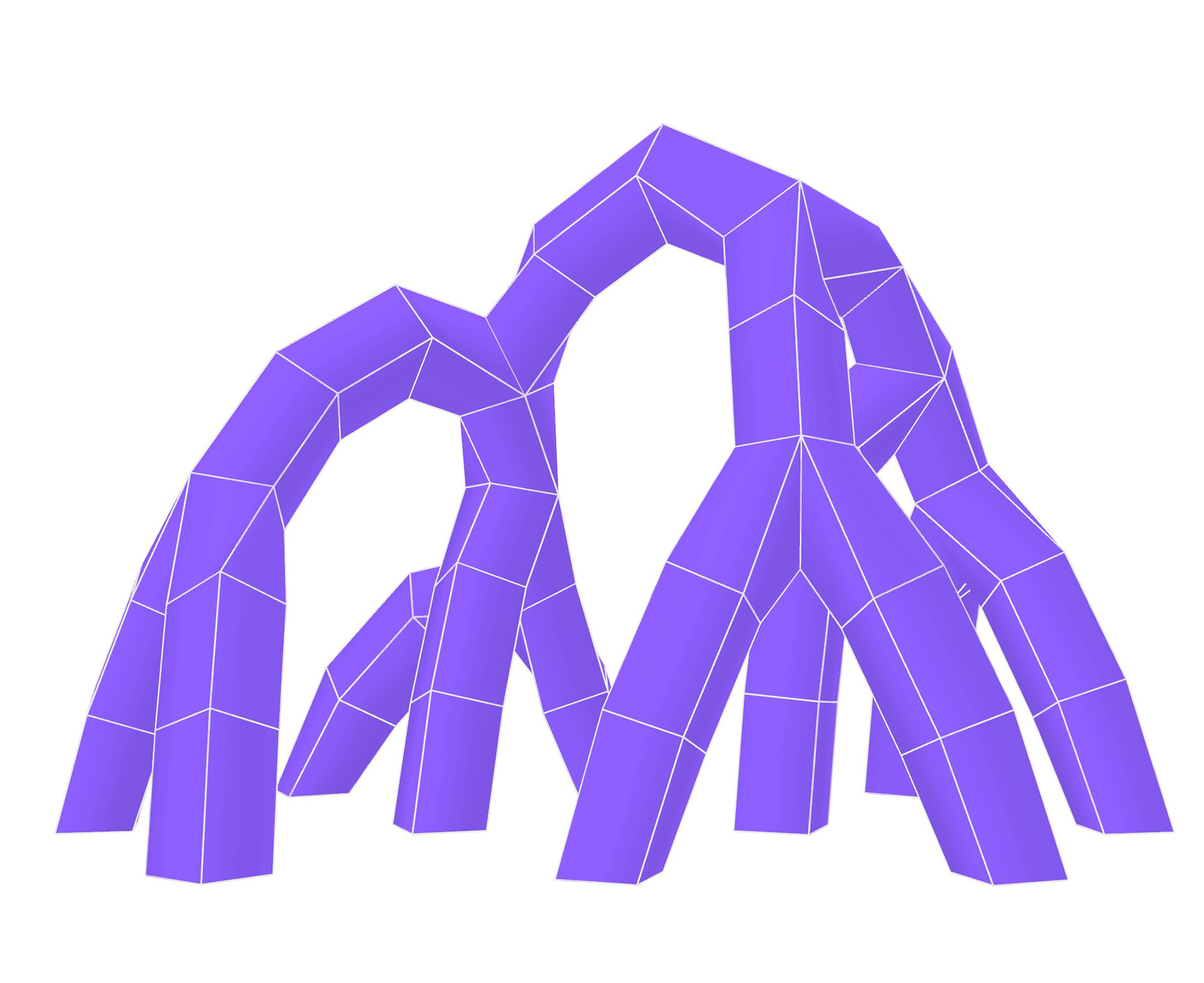
2. Thicken lines(Using Mesh Fattener or Multipipe by Daniel Piker)
3. Dispatch complex(vertex valence > 4) and simple regions

4. Divide regions into panels. The panels will be reconstructed as patch mesh for unroll purpose.
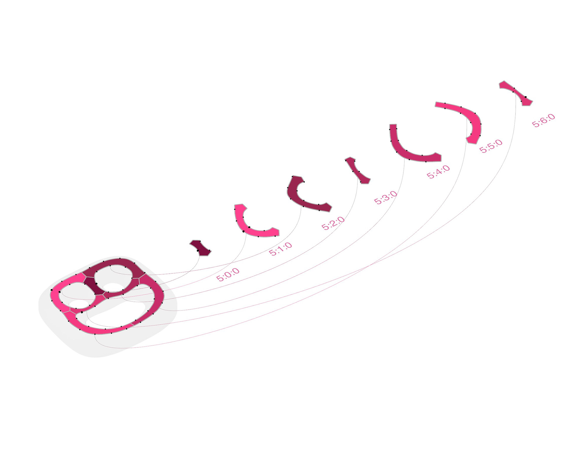
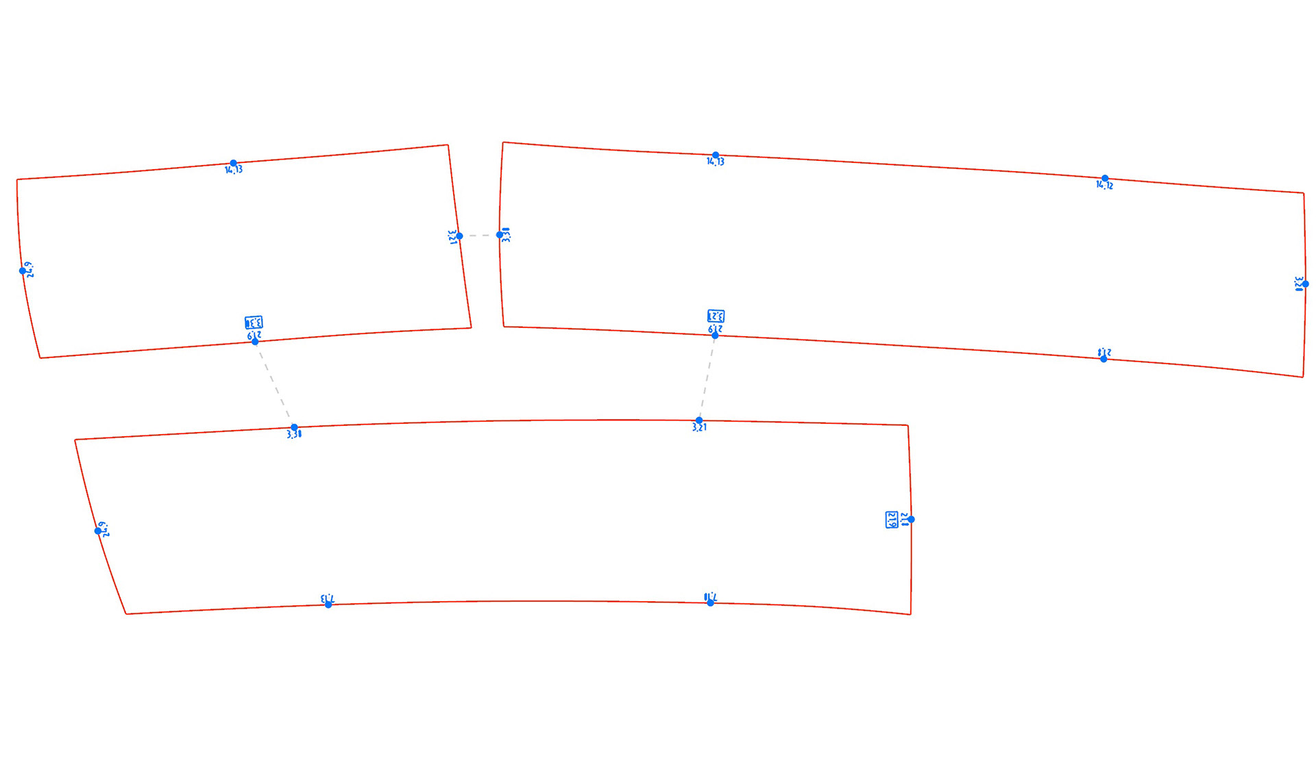
Assembly Guide II: Neighbor Search
The diagram and animation below show the neighbor relationship and the example file of the
cutting and plotting profiles. This feature assists fabricator to quickly index the neighbor pieces
If you are interested in the my thinking process, please take a look at the log HERE.
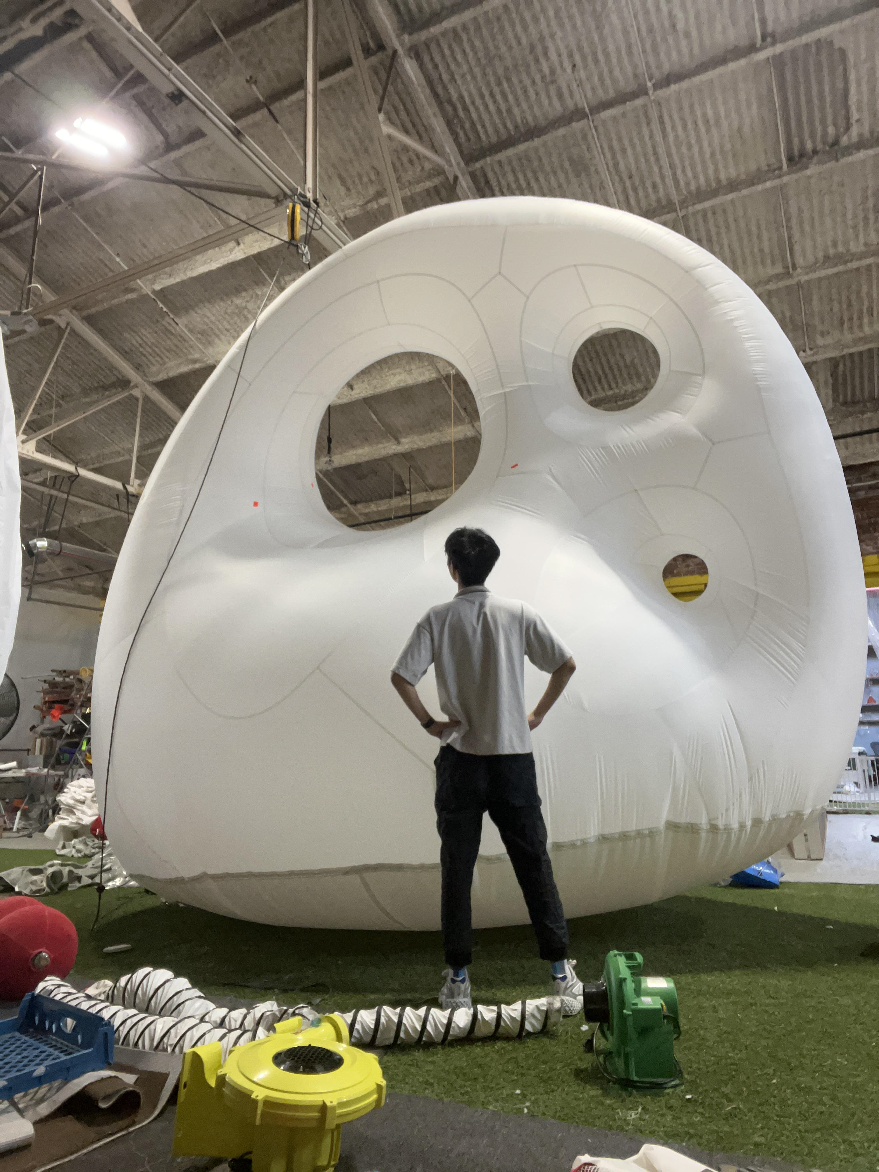
One example of the closed planar boundaries geometry - a cloud bubble.
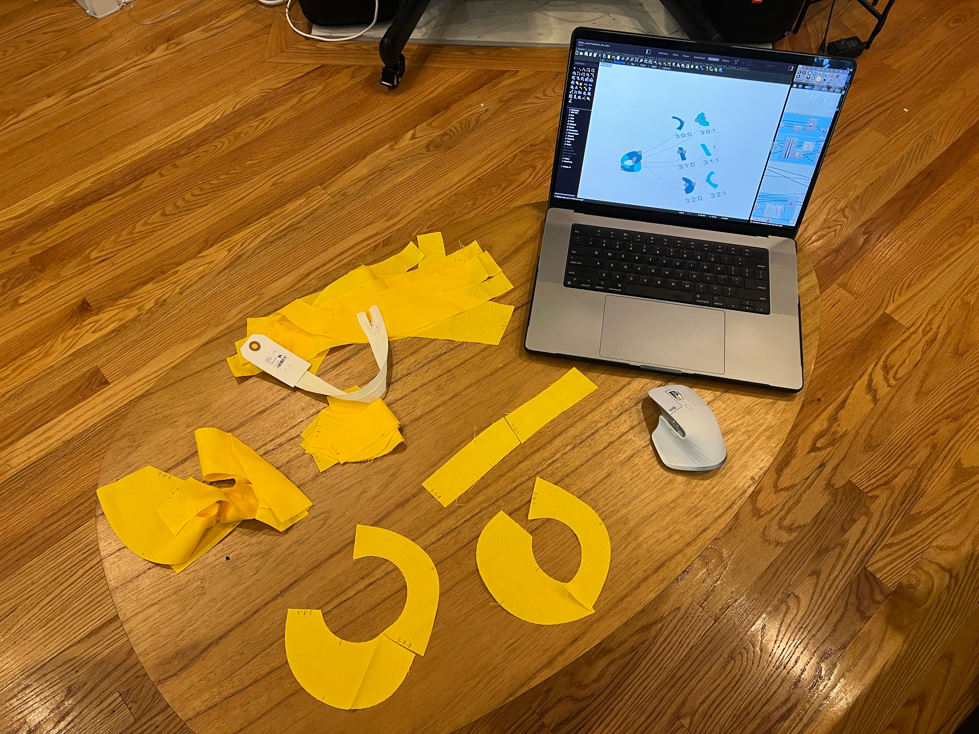
Below is another example of the first logic: CLOUD Pillow
You can check the process on my How to Make (almost) Anything site.
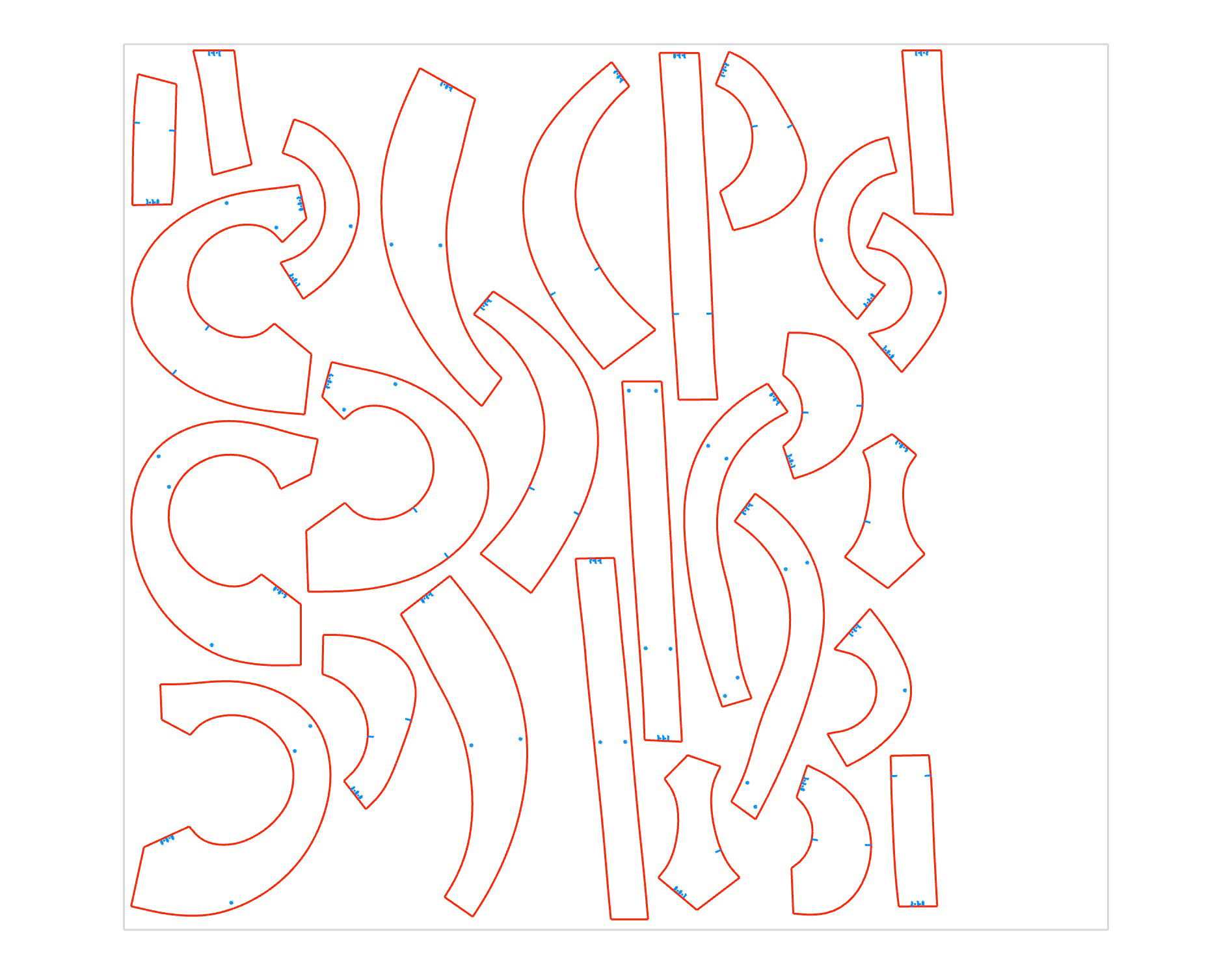
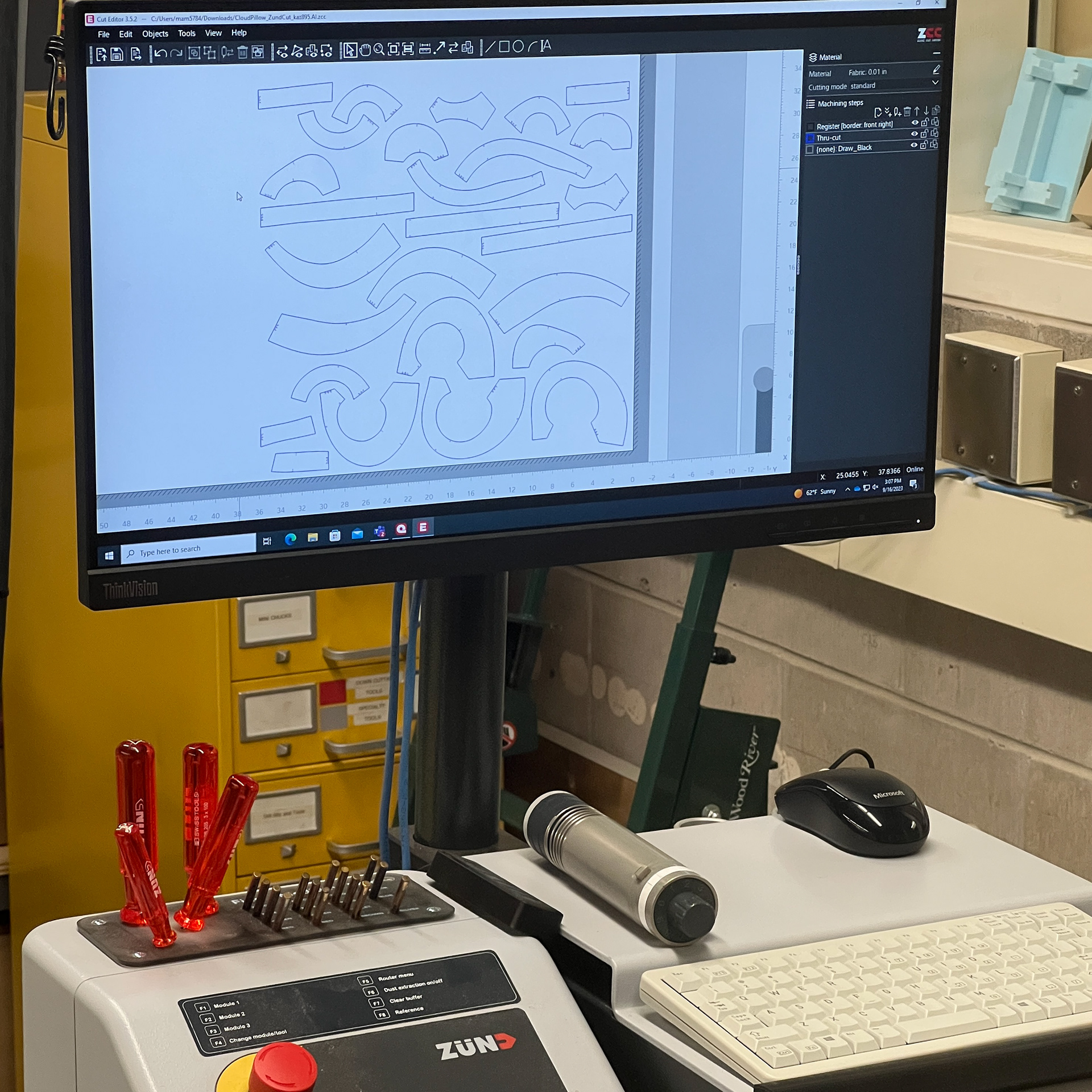
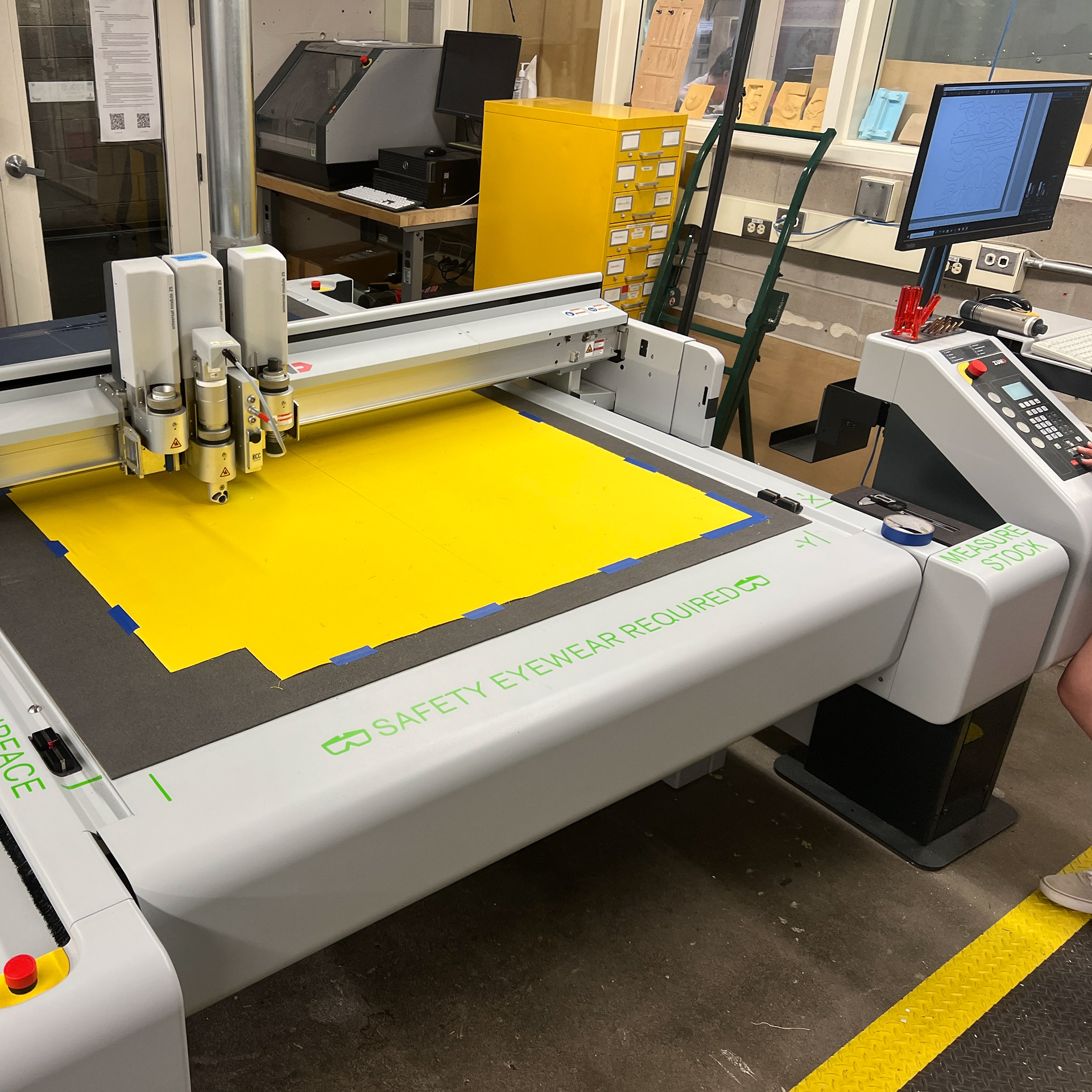

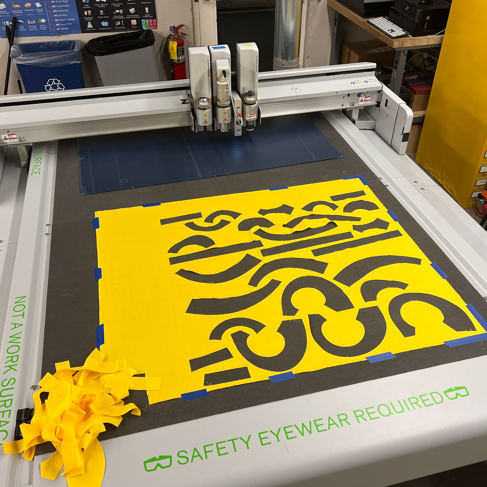
↑ : Perfect machine cutting
↓ : Terrible human sewing
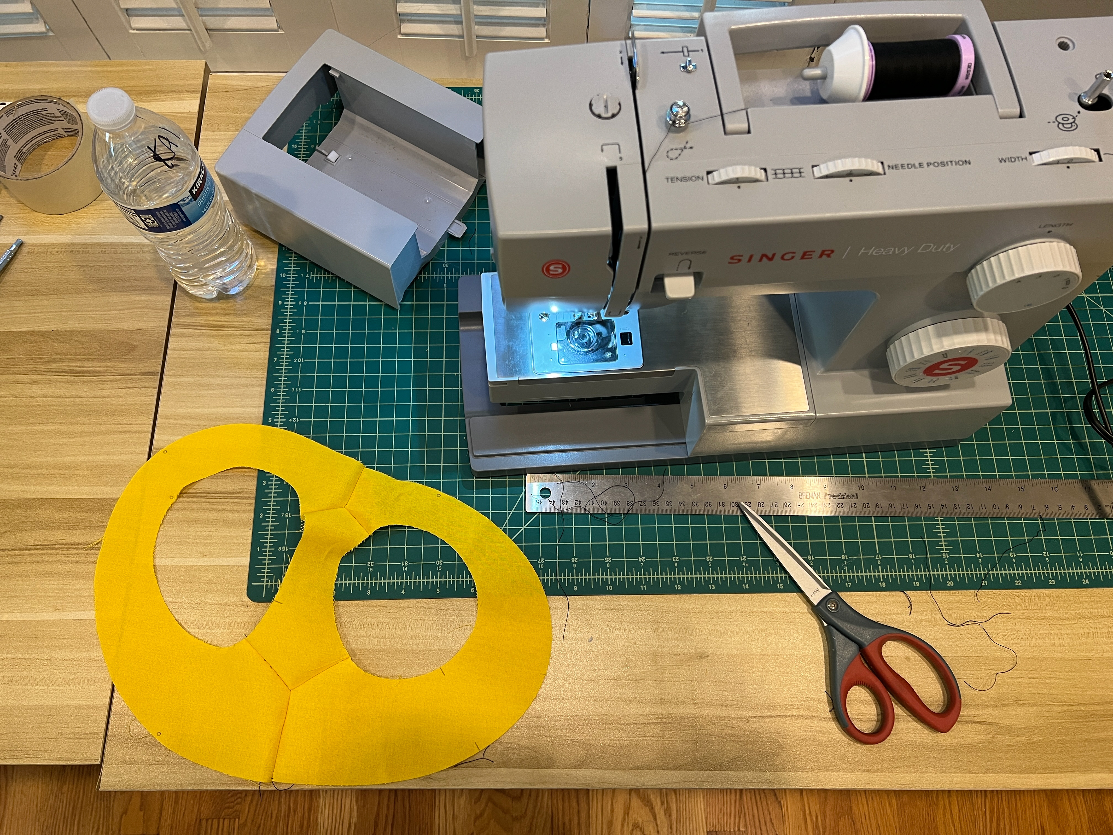
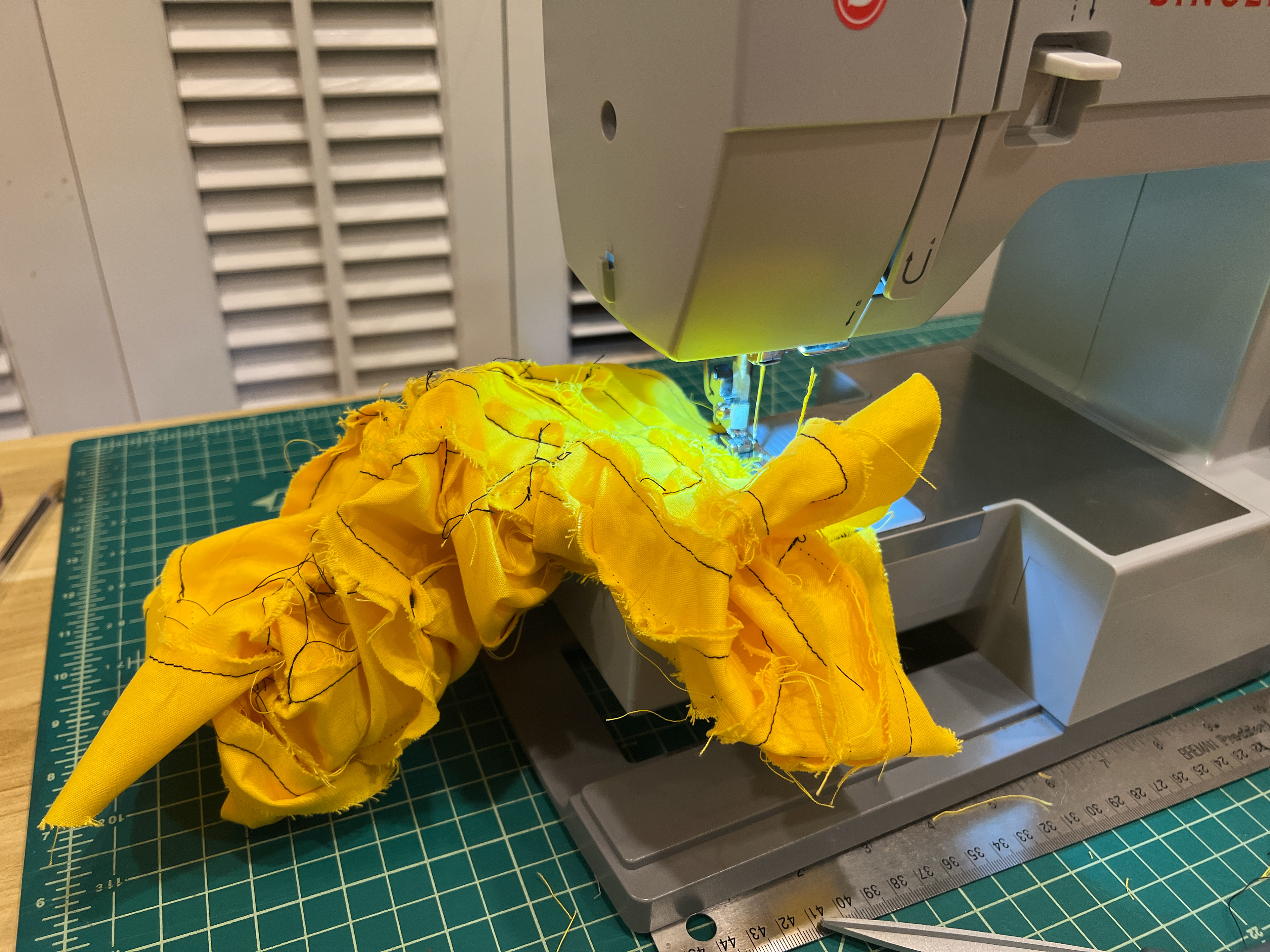
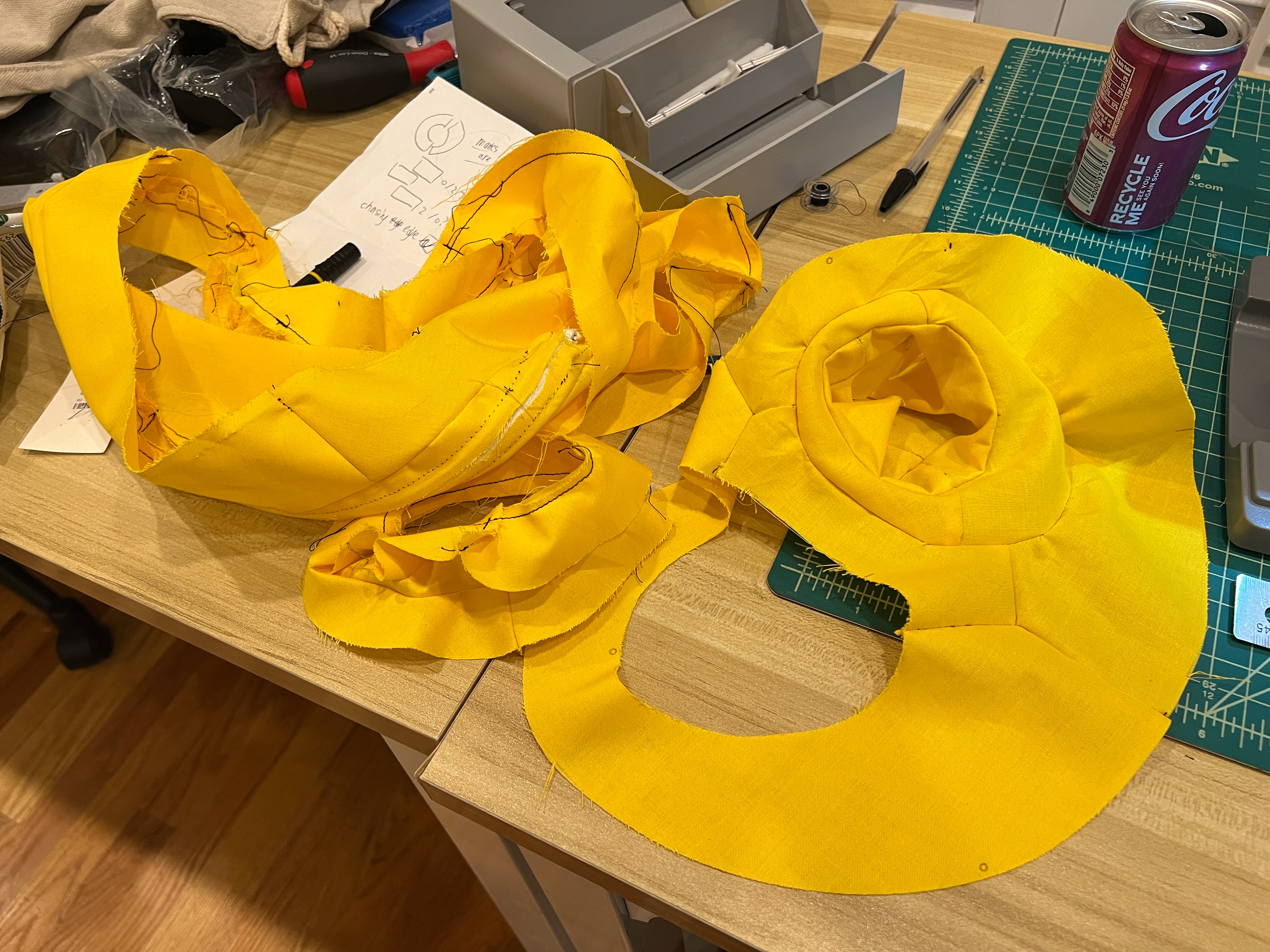
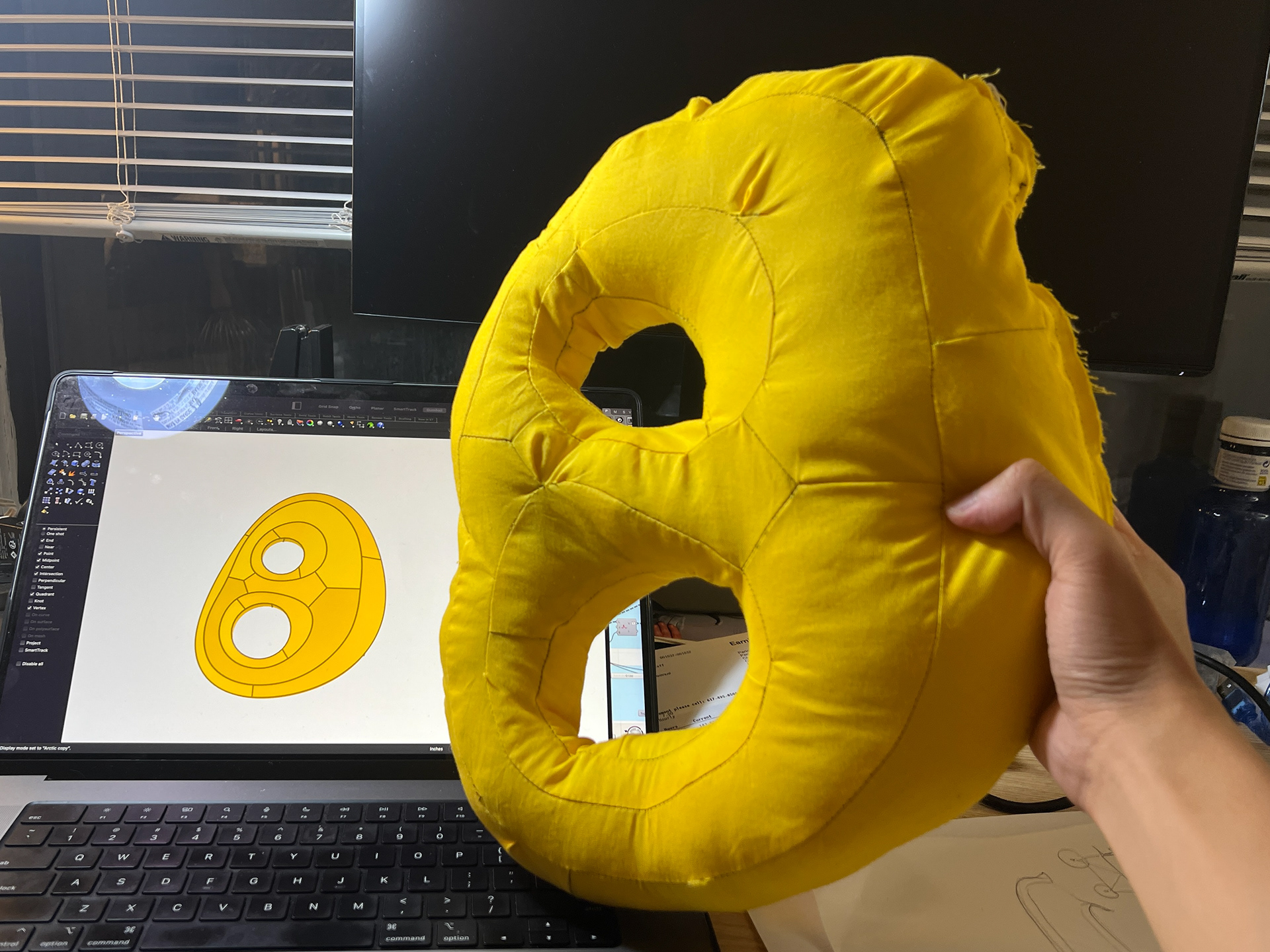
bad sewing execution --- but demonstrated the idea!
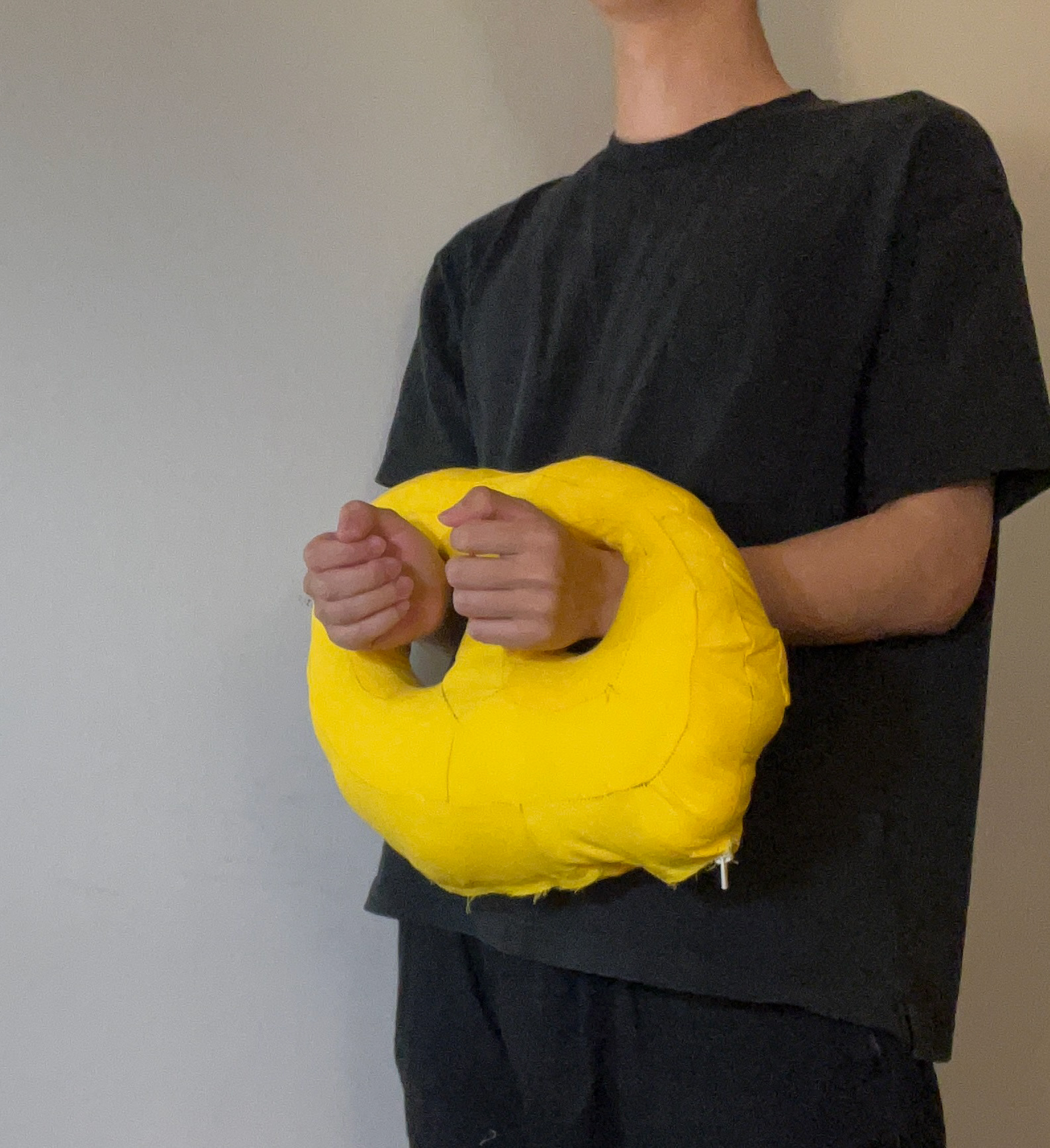
could be a cute and useless handcuff